Filling the Need for Rationalization and Energy Efficiency
As a result of the recent demands for a more streamlined and energy-efficient approach to bridge and framework construction, the use of steel and concrete composites is on the increase. Furthermore, the introduction of performance planning has resulted in a need for research into more rational constructions. In order, therefore, to satisfy these needs, it is necessary to carry out testing to confirm suitability when new building products are being studied and researched.
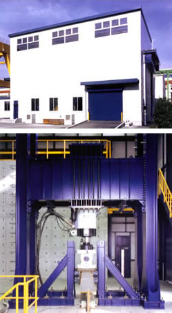
In November 2001, Komai Tekko Inc. completed the installation of a fully-fledged testing facility featuring reaction walls, reaction floors, and other equipment such as a 1,300-kN dynamic load tester. In addition to the wind-resistance research and oscillation-prevention techniques which are made possible by our wind-tunnel facility, this new installation now allows structures to be dynamically tested to confirm their resistance to repeated loading. Accordingly, we can now offer complete technical support for the resolution of problems relating to dynamic loading, and whenever new building types or styles are to be used, prototypes are created so that strength can be confirmed using this test equipment.
Of the various strength parameters applicable to bridges and other constructions, it is crucial that the fatigue strength ? that is, the resistance to repeated loading by automobiles, trains, and the like ? be increased in order to extend the service life. Our dynamic testing facility can be used to efficiently confirm this strength through high-speed repeated loading, and we intend to continue utilizing this equipment to its maximum in active research and development of more-rational bridges and other constructions.
